Saturday May 14th 2011
Attendance: 2
After the excitement of the first start-ups a fortnight ago the emphasis is now on getting as much of the remaining mechanical, electrical and bodywork done before the loco is shunted into Buckley Wells shed to begin the repaint, there is still much to be done.
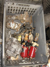
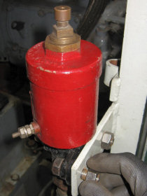
Jason began with the most urgent job on his list, to sort and fit the auxiliary pneumatic vales that attach to the L/H rear side frame - these mostly control the gear change mechanism on the Voith transmission and need fitting to allow the pneumatic pipework to be completed. Alan Lee had placed all the valves in a plastic box during a clearup, ready for when they would be needed. Jason collected three Westinghouse Electro-Pneumatic (EP) valves and two small relay valves. These were taken into the support coach, cleaned/drelled as necessary including running a tap and die on the threads and suitable mounting nuts/bolts sourced. The cleaned valves were test fitted successfully using reference photos of the setup on classmate D9526, resident at the West Somerset Railway.
 |
 |
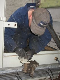 |
| Auxiliary Pneumatic Valves | Fitted Pneumatic Valve | Jason fitting valves |
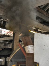
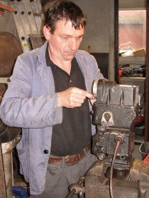
Alan Lee arrived and got on with fixing snags found during the start-up two weeks ago. The starter circuit which had caused problems had been traced to a wiring fault in the starter motor contact switch. This was rewired, curing the fault so that the engine starts easily. The rest of Alan's day was spent on the Engine governor, investigating the fast and slightly uneven tickover. The spare governor from the original power unit was clamped into the vice on the workshop bench then, using the manual for reference, dismantled to see exactly how it worked and how to make adjustments, also meaning the spare had an inspection, clean and light overhaul. Once happy, Alan was able to adjust the governor fitted to the locomotive's new Paxman power unit.
 |
 |
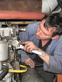 |
| Loco started following start contact rewire | Alan stripping the spare governor | Alan working on the in-situ governer |
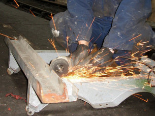
Whilst fitting the air valves, Jason had noticed the auxiliary air tank frame wasn't seated properly on its mounting. Investigation found this was caused by a piece of flat bar, welded in across the underframe as a modification, which partly fouled the underside tank frame. A clearance notch was required, so this was marked and the bar unbolted and removed to the floor where an angle grinder was used to cut out the notch. With the modified bar refitted, the air tank frame seated properly onto its mounting. Another air system component requiring a home was the Davies & Metcalf Drip trap (or Condenser), Jason sussed out a likely position for this and then set about making a mounting bracket to suit. Some left over cable channel section was used for this, a suitable length being cut with the angle grinder, holes marked then drilled and finally the condenser fitted to the bracket.
After lunch Jason went into 'Paddy' to have a look at the nose end doors that had been removed for headcode box alterations. Once liberated from stores a drill was run through the hinge holes and the doors were taken round to the loco and mounted back into position. Meanwhile, Alan had finished with preliminary governor adjustments and, after inspecting the brushes and armature of the 110v generator, switched in the batteries and fired up the loco. The engine roared into life with no problems although some frustrated looks were noted from the workers of Ian Riley engineering who, having clanged and banged all morning, were now working quietly and listening to the football on the radio! Alan soon shut the engine down and continued to make more adjustments to the governor, he started the engine 10 times throughout the afternoon, the loco sounding smoother and sweeter each time.
 |
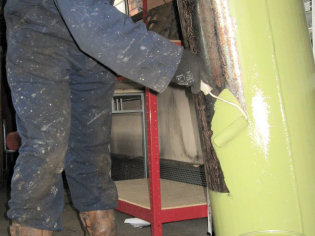 |
| Jason cutting a clearance notch | Jason painting the aux air tank |
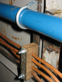
Working down his 'to-do' list, Jason was looking to fashion some new pipe clamps (or cleats) for the thin copper cooling system bleed pipes and to incorporate a fixing for the large main coolant pipe. The pipes are currently dangling freely but need to be clamped up and supported by the 'A' end bonnet roof. After making some measurements Jason cut some short lengths of 1" angle iron to form the brackets and used some pallet wood cut into short blocks to form clamps; holes were drilled into the blocks for the pipes and then cut into halves. Mounting holes were then drilled on the brackets and blocks to finalise the construction process, ready for fitting.
Whilst making adjustments Alan had discovered that the throttle setting springs in the governor were of a different type, giving the power unit a fast tick-over. This is not necessary for rail traction use, so the spare governor unit will need to be further dismantled to hopefully remove and transfer the correct throttle springs into the new unit. Jason finished off his day applying a coat of green anti-corrosive paint to the Auxiliary air tank that had been drelled during a previous work session.
Sunday May 15th 2011
Attendance: 5
Jason began by applying a coat of grey primer to the auxiliary air tank he had treated with anit-corrosive paint yesterday. He was soon joined by Jim Gough, Graham Mortimore, Kris Mason & Dave Garnett, allowing Jason to set off on a shopping trip to Halfords. Kris removed the bellows from the air filet housing to the turbo inlet, an internal wire frame needs to be inserted to prevent collapse when the engine is throttled up to full, access is tight for some of this job with Kris working between the power unit and the vacuum exhausters. Graham set to work cutting and drilling brackets for the air tank mounting brace bars and Dave assisted Jim setting up the welder to begin welding the brace brackets into place.
Jason returned from Halfords with 9 exhaust 'U' bolt clamps, 6 for use on the air aftercooler pipework and 3 to hold the main coolant feed pipe sharing the mountings for the bleed pipe cleats made yesterday. Jason drilled out the holes for the 'U' clamps then assigned Kris his next job cleaning up the main air reservoir tanks (Ex-Class 86) which were covered in brown crud. Kris attacked the first of the large tanks using a paint scraper as suggested to remove the large surface deposits so that the tanks could be later skimmed over with a sanding disk to for a key ready for painting.
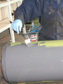 |
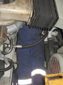 |
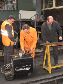 |
| Jason applying more paint to the aux tank | Kris having fun with the bellows | Dave, Graham and Jim setting up |
With the coolant and bleed pipe clamps now ready to install, Jason went about fitting the three of them from nose end upto the cab. Unfortunately this uncovered a problem at the cab end where the pipes attach to the header tank; when the pipes were installed they were laid out and looked OK, however, since then the 'A' end roof section has been returned and the pipes have been compressed downwards meaning they are now longer than required. This resulted in a "S" bend forming at the header tank end as the slack became greater and this was further increased as the pipes were clamped and straightened through the cleat blocks with the "S" bend becoming a substantial "Ox bow".
To fix the problem, Jason had to drain the header tank, slacken the jubilee clips at the joints, measure and cut the copper pipe, then, using a blow torch and soldering equipment, de-solder the pipe end from the off cuts and re-solder them to the trimmed pipe ends, all whilst being perched on top of the bonnet and working through the small rectangular horn box aperture. As well as the small working space, this was rather difficult due to working 'uphill' causing the molten solder to drop away from the joints with gravity, but Jason battled on and managed to replumb and refit all the pipes, removing the "Ox bow" to his satisfaction.
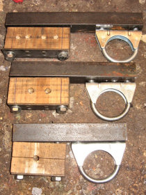 |
 |
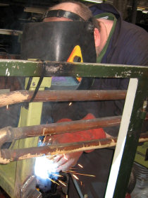 |
| Cleats and clamps ready for fitting | Cleats and clamp installed | Jim welding on the main air tank frame |
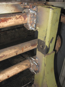
After lunch Graham joined Kris scraping down the large air tanks, Jim & Dave began welding the air aftercooler clamps onto the air tank frames and, once complete, the aftercooler pipe was installed successfully. Jim then moved on to welding the pipe cleat brackets to the underside of the bonnet roof section, not the easiest of jobs when the bonnet roof is back on the loco with access through the bonnet door and a squeeze over the top of the engine!
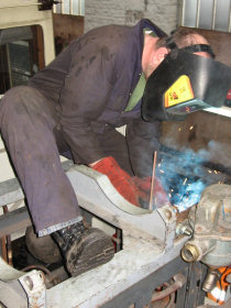
The final task for the day was to figure out where to mount the condenser brackets in the B end which, with the dual brake modifications that have been carried out, needed some discussion as space is at a premium! Eventually it was decided to mount the condenser close to the outlet of the air aftercooler pipe, and Jim did the welding honours. Kris & Graham had been working well together and had managed to clean off the first of the large air tanks and make headway with the second although rain had set in and the pair were working in the confined space underneath the support coach.
 |
 |
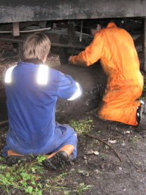 |
| Air aftercooler clamped into position | Jim welding a condenser bracket | Kris and Graham scraping out of the rain |
With most of the work planned for the weekend complete, tools were picked up and tidied away and 'Team Ernest' disbanded until next time. There's still more to do but D9531 is edging steadily towards completion with every session.
If you'd like to get involved as a volunteer or make a donation click here for details.
< Prev | Workgroup Reports | Next >